Arduino - Actuador con retroalimentación

En un tutorial anterior, hemos aprendido sobre el actuador lineal sin retroalimentación. En este tutorial, vamos a aprender sobre el actuador lineal con retroalimentación (también conocido como el actuador lineal con retroalimentación). La retroalimentación del actuador lineal proporciona la información para identificar la posición de su recorrido y luego controlar la posición. En detalle, vamos a aprender:

Acerca del actuador lineal con realimentación

Un actuador lineal con retroalimentación es un actuador lineal que tiene una señal de retroalimentación que permite identificar su posición y controlarlo. La retroalimentación es un potenciómetro que genera un voltaje proporcional a la posición del recorrido.

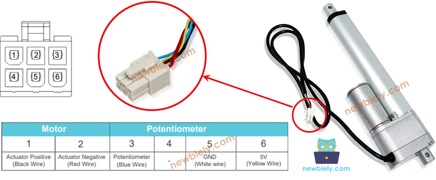
Pinout del actuador lineal de retroalimentación

Un actuador lineal de retroalimentación tiene 5 cables:

  • Cable positivo del actuador: Este cable se utiliza para controlar el actuador lineal utilizando voltaje alto (12V, 24V, 48V...).
  • Cable positivo del actuador: Este cable se utiliza para controlar el actuador lineal utilizando voltaje alto (12V, 24V, 48V...).
  • Cable de 5V: Este cable se utiliza para el potenciómetro de retroalimentación. Conecte este cable a 5V o 3.3V.
  • Cable de tierra: Este cable se utiliza para el potenciómetro de retroalimentación. Conecte este cable a tierra.
  • Cable del potenciómetro: (también llamado cable de retroalimentación, o cable de salida) Este cable proporciona el valor de voltaje en proporción a la posición del recorrido.
Pinout del actuador lineal con retroalimentación

Cómo funciona

Si proporcionamos alta tensión a los cables positivos y negativos, el recorrido del actuador se extenderá o retraerá. En detalle, si conectamos:

  • 12 V (12 V, 24 V, 48 V, ...) y GND al cable positivo y al cable negativo, respectivamente: el actuador lineal se extiende a plena velocidad hasta que alcance el tope.
  • 12 V (12 V, 24 V, 48 V, ...) y GND al cable negativo y al cable positivo, respectivamente: el actuador lineal se retrae a plena velocidad hasta que alcance el tope.
  • Mientras se extiende o se retrae, si dejamos de alimentar al actuador (GND a ambos cables, positivo y negativo), el actuador deja de extenderse/retraerse.

※ Nota:

  • El valor de voltaje para controlar el actuador depende de la especificación del actuador. Consulte la hoja de datos o el manual para conocer el valor de voltaje correspondiente.
  • El actuador puede mantener la posición incluso cuando se detiene la alimentación mientras soporta una carga.

El valor de voltaje en el potenciómetro es proporcional a la posición de la carrera del actuador. Al medir este voltaje, podemos conocer la posición de la carrera.

Diagrama de cableado

Por favor, retire los tres jumpers del módulo L298N antes de cablear.

Diagrama de cableado del controlador L298N para actuador lineal de Arduino

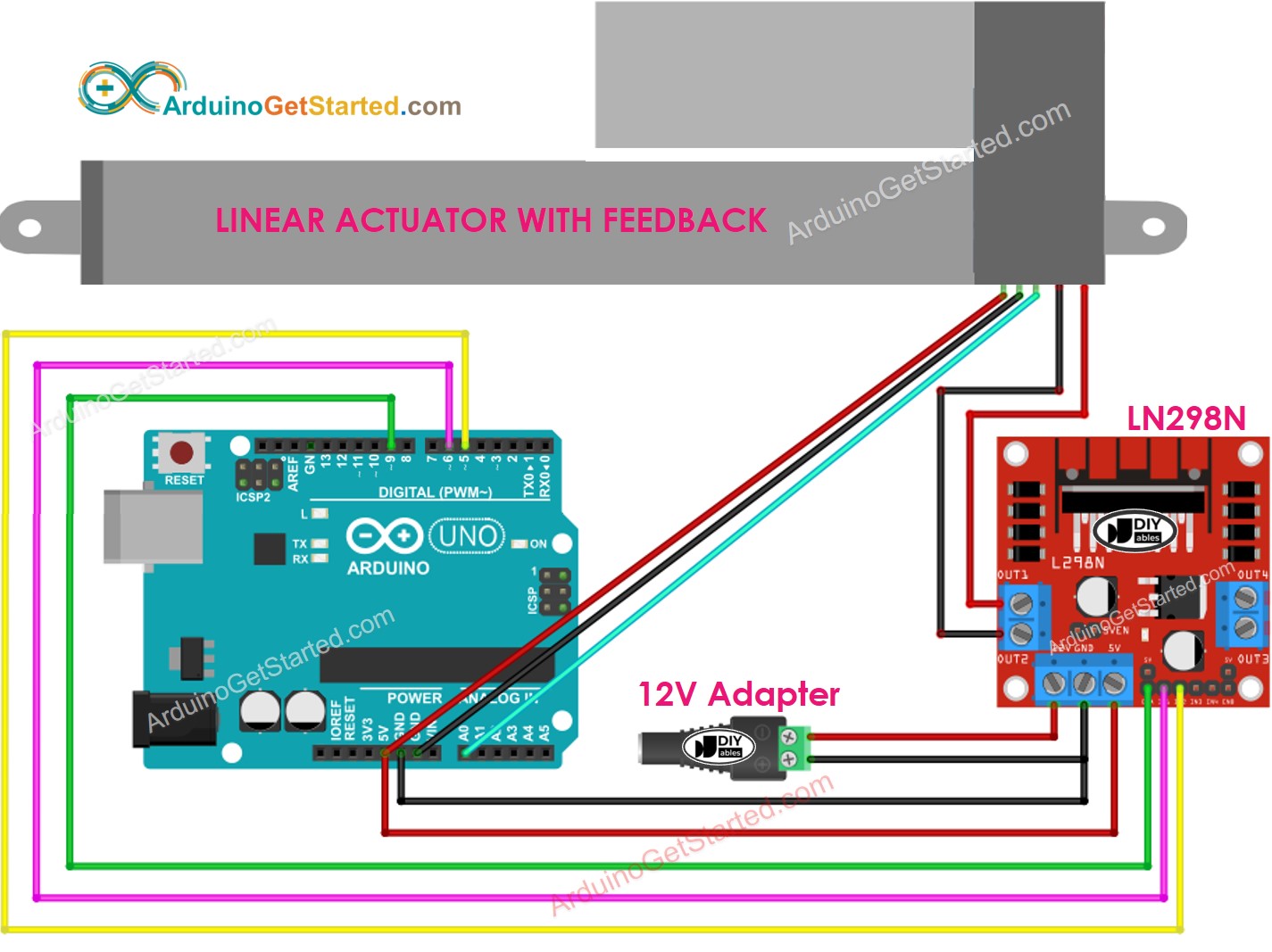
This image is created using Fritzing. Click to enlarge image

Cómo controlar la extensión y la retracción de un actuador lineal

Ver Arduino - Actuador tutorial

Cómo encontrar la posición del actuador lineal

A continuación se muestra cómo identificar la posición del recorrido en un actuador lineal.

Calibración

  • Identifica la longitud del recorrido del actuador (en milímetros) midiendo (con una regla) o leyendo la hoja de datos
  • Identifica los valores de salida cuando el actuador lineal está completamente extendido y completamente retraído al ejecutar el código que se muestra a continuación
/* * Este código de Arduino fue desarrollado por es.newbiely.com * Este código de Arduino se proporciona al público sin ninguna restricción. * Para tutoriales completos y diagramas de cableado, visite: * https://es.newbiely.com/tutorials/arduino/arduino-actuator-with-feedback */ // the code for getting the feedback when the actuator fully extended and retracted #define ENA_PIN 9 // the Arduino pin connected to the EN1 pin L298N #define IN1_PIN 6 // the Arduino pin connected to the IN1 pin L298N #define IN2_PIN 5 // the Arduino pin connected to the IN2 pin L298N #define POTENTIOMETER_PIN A0 // the Arduino pin connected to the potentiometer of the actuator void setup() { Serial.begin(9600); // initialize digital pins as outputs. pinMode(ENA_PIN, OUTPUT); pinMode(IN1_PIN, OUTPUT); pinMode(IN2_PIN, OUTPUT); digitalWrite(ENA_PIN, HIGH); } void loop() { // extend the actuator digitalWrite(IN1_PIN, HIGH); digitalWrite(IN2_PIN, LOW); delay(20000); // wait for actuator fully extends. It will stop extending automatically when reaching the limit // read the analog in value: int POTENTIOMETER_MAX = analogRead(POTENTIOMETER_PIN); Serial.print("POTENTIOMETER_MAX = "); Serial.println(POTENTIOMETER_MAX); // retracts the actuator digitalWrite(IN1_PIN, LOW); digitalWrite(IN2_PIN, HIGH); delay(20000); // wait for actuator fully extends. It will stop retracting automatically when reaching the limit int POTENTIOMETER_MIN = analogRead(POTENTIOMETER_PIN); Serial.print("POTENTIOMETER_MIN = "); Serial.println(POTENTIOMETER_MIN); }
  • Verás el registro en el Monitor Serial como en el siguiente ejemplo
COM6
Send
POTENTIOMETER_MAX = 987 POTENTIOMETER_MIN = 13
Autoscroll Show timestamp
Clear output
9600 baud  
Newline  
  • Anota estos valores
  • Si los valores mínimos y máximos están invertidos, intercambia IN1_PIN e IN2_PIN
  • Actualiza tres valores en el código de abajo
  • Código de Arduino que calcula la posición del actuador

    /* * Este código de Arduino fue desarrollado por es.newbiely.com * Este código de Arduino se proporciona al público sin ninguna restricción. * Para tutoriales completos y diagramas de cableado, visite: * https://es.newbiely.com/tutorials/arduino/arduino-actuator-with-feedback */ #define ENA_PIN 9 // the Arduino pin connected to the EN1 pin L298N #define IN1_PIN 6 // the Arduino pin connected to the IN1 pin L298N #define IN2_PIN 5 // the Arduino pin connected to the IN2 pin L298N #define POTENTIOMETER_PIN A0 // the Arduino pin connected to the potentiometer of the actuator #define STROKE_LENGTH 102 // PLEASE UPDATE THIS VALUE (in millimeter) #define POTENTIOMETER_MAX 987 // PLEASE UPDATE THIS VALUE #define POTENTIOMETER_MIN 13 // PLEASE UPDATE THIS VALUE void setup() { Serial.begin(9600); // initialize digital pins as outputs. pinMode(ENA_PIN, OUTPUT); pinMode(IN1_PIN, OUTPUT); pinMode(IN2_PIN, OUTPUT); digitalWrite(ENA_PIN, HIGH); } void loop() { // extend the actuator digitalWrite(IN1_PIN, HIGH); digitalWrite(IN2_PIN, LOW); int potentiometer_value = analogRead(POTENTIOMETER_PIN); int stroke_pos = map(potentiometer_value, POTENTIOMETER_MIN, POTENTIOMETER_MAX, 0, STROKE_LENGTH); Serial.print("The stroke's position = "); Serial.print(stroke_pos); Serial.println(" mm"); }
    • Actualizar los tres valores calibrados en el código
    • Cargar el código en Arduino
    • Ver el resultado en el Monitor serie
    COM6
    Send
    The stroke's position = 2 mm The stroke's position = 35 mm The stroke's position = 43 mm The stroke's position = 60 mm The stroke's position = 68 mm The stroke's position = 79 mm The stroke's position = 83 mm The stroke's position = 96 mm The stroke's position = 100 mm
    Autoscroll Show timestamp
    Clear output
    9600 baud  
    Newline  

    Cómo controlar un actuador lineal para alcanzar una posición específica

    /* * Este código de Arduino fue desarrollado por es.newbiely.com * Este código de Arduino se proporciona al público sin ninguna restricción. * Para tutoriales completos y diagramas de cableado, visite: * https://es.newbiely.com/tutorials/arduino/arduino-actuator-with-feedback */ #define ENA_PIN 9 // the Arduino pin connected to the EN1 pin L298N #define IN1_PIN 6 // the Arduino pin connected to the IN1 pin L298N #define IN2_PIN 5 // the Arduino pin connected to the IN2 pin L298N #define POTENTIOMETER_PIN A0 // the Arduino pin connected to the potentiometer of the actuator #define STROKE_LENGTH 102 // PLEASE UPDATE THIS VALUE (in millimeter) #define POTENTIOMETER_MAX 987 // PLEASE UPDATE THIS VALUE #define POTENTIOMETER_MIN 13 // PLEASE UPDATE THIS VALUE #define TOLERANCE 5 // in millimeter int targetPosition_mm = 50; // in millimeter void setup() { Serial.begin(9600); // initialize digital pins as outputs. pinMode(ENA_PIN, OUTPUT); pinMode(IN1_PIN, OUTPUT); pinMode(IN2_PIN, OUTPUT); digitalWrite(ENA_PIN, HIGH); } void loop() { int potentiometer_value = analogRead(POTENTIOMETER_PIN); int stroke_pos = map(potentiometer_value, POTENTIOMETER_MIN, POTENTIOMETER_MAX, 0, STROKE_LENGTH); Serial.print("The stroke's position = "); Serial.print(stroke_pos); Serial.println(" mm"); if (stroke_pos < (targetPosition_mm - TOLERANCE)) ACTUATOR_extend(); else if (stroke_pos > (targetPosition_mm + TOLERANCE)) ACTUATOR_retract(); else ACTUATOR_stop(); } void ACTUATOR_extend() { digitalWrite(IN1_PIN, HIGH); digitalWrite(IN2_PIN, LOW); } void ACTUATOR_retract() { digitalWrite(IN1_PIN, LOW); digitalWrite(IN2_PIN, HIGH); } void ACTUATOR_stop() { digitalWrite(IN1_PIN, LOW); digitalWrite(IN2_PIN, LOW); }

    Video Tutorial

    Estamos considerando crear tutoriales en video. Si considera que los tutoriales en video son importantes, suscríbase a nuestro canal de YouTube para motivarnos a crear los videos.

    Referencias de Funciones

    Tutoriales Relacionados

    ※ NUESTROS MENSAJES

    • No dude en compartir el enlace de este tutorial. Sin embargo, por favor no use nuestro contenido en otros sitios web. Hemos invertido mucho esfuerzo y tiempo en crear el contenido, ¡por favor respete nuestro trabajo!