ESP32 - LED - Parpadeo sin retardo
Uno de los primeros programas que ejecutan los principiantes es parpadear un LED. La forma más simple de parpadear un LED es usar la función delay(). Esta función bloquea al ESP32 y evita que haga otras cosas. Está bien si solo quieres parpadear un único LED. Sin embargo, si quieres parpadear más LEDs o realizar otras tareas en paralelo, no puedes usar la función delay(). Necesitamos otra solución. Este tutorial te enseña cómo realizar múltiples tareas sin usar la función delay. Más específicamente, aprenderemos a parpadear un LED y a comprobar el estado del botón.
Vamos a repasar los tres ejemplos que se muestran a continuación y comparar las diferencias entre ellos.
- ESP32 parpadea un LED usando la función delay()
- ESP32 parpadea un LED usando la función millis()
- ESP32 parpadea un LED usando la biblioteca ezLED
Este método se puede aplicar para permitir que el ESP32 realice varias tareas al mismo tiempo. El parpadeo del LED es solo un ejemplo.
Hardware Requerido
Or you can buy the following kits:
| 1 | × | DIYables ESP32 Starter Kit (ESP32 included) | |
| 1 | × | DIYables Sensor Kit (30 sensors/displays) | |
| 1 | × | DIYables Sensor Kit (18 sensors/displays) |
Buy Note: Use the LED Module for easier wiring. It includes an integrated resistor.
Acerca de LED y Botón
Tenemos tutoriales específicos sobre LED y botón. Cada tutorial contiene información detallada e instrucciones paso a paso sobre el pinout del hardware, el principio de funcionamiento, la conexión de cableado al ESP32, el código para ESP32... Obtén más información sobre ellos en los siguientes enlaces:
Diagrama de Cableado
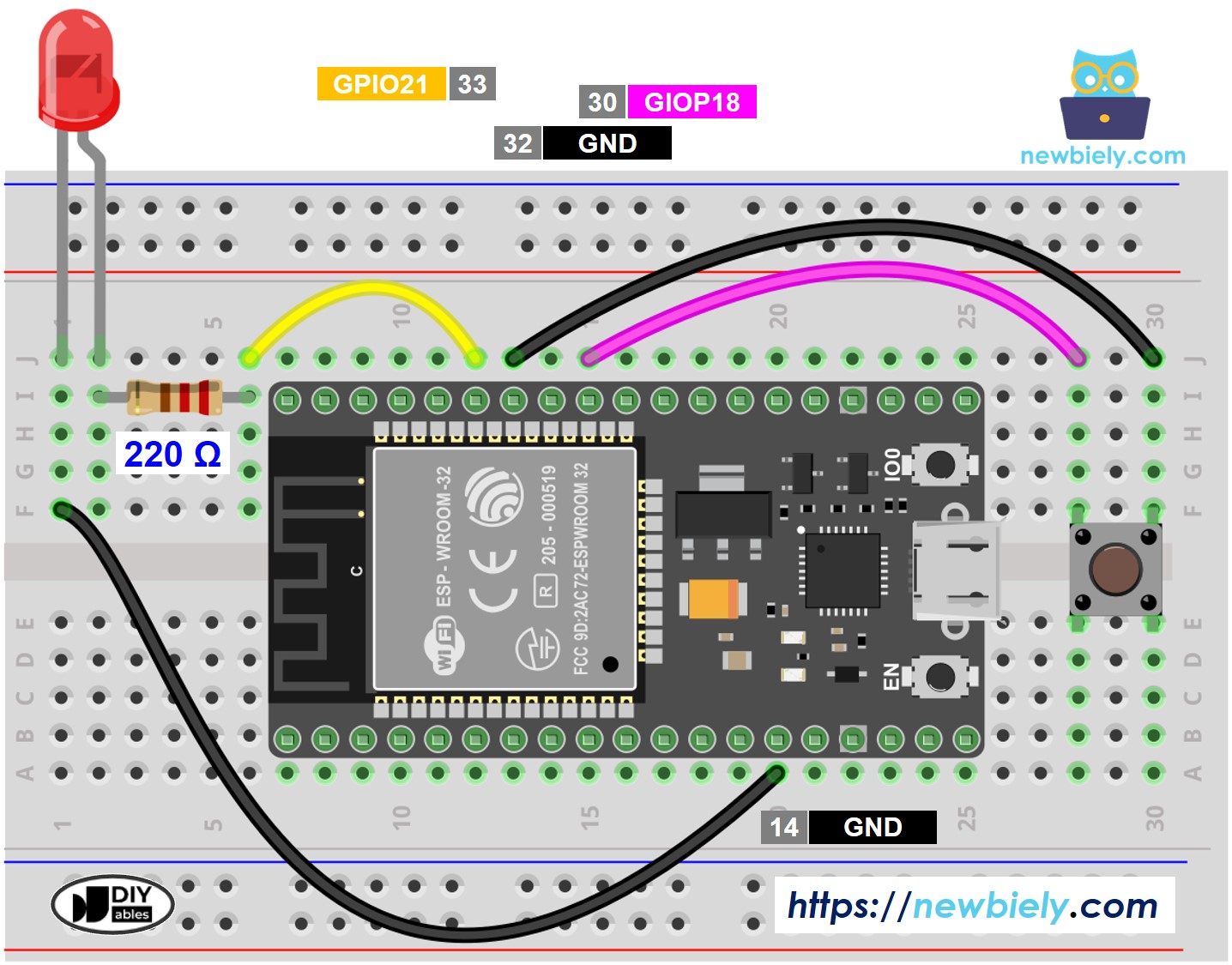
This image is created using Fritzing. Click to enlarge image
Si no sabe c\u00f3mo alimentar ESP32 y otros componentes, encuentre instrucciones en el siguiente tutorial: C\u00f3mo alimentar ESP32.
Comparémos el código de ESP32 que hace parpadear un LED con y sin usar la función delay()
Código ESP32 - Con Retraso
Pasos R\u00e1pidos
- Si es la primera vez que usas ESP32, consulta cómo configurar el entorno para ESP32 en Arduino IDE.
- Realiza el cableado como se muestra en la imagen anterior.
- Conecta la placa ESP32 a tu PC mediante un cable micro USB.
- Abre Arduino IDE en tu PC.
- Selecciona la placa ESP32 correcta (p. ej. ESP32 Dev Module) y el puerto COM.
- Copia el código anterior y pégalo en Arduino IDE.
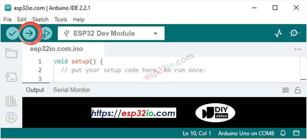
- Compila y sube el código a la placa ESP32 haciendo clic en el botón Subir en Arduino IDE.
- Abrir el Monitor Serial en el IDE de Arduino

- Presiona el botón 4 veces
- Observa el LED: El LED alterna entre ENCENDIDO y APAGADO periódicamente cada segundo
- Observa la salida en el Monitor serie
- En el Monitor Serial, no verás que el estado cambie a 0 cuatro veces. Eso se debe a que, durante el tiempo de retardo, el ESP32 NO PUEDE detectar el cambio.
Código ESP32 - Sin retraso
Pasos R\u00e1pidos
- Si es la primera vez que usa ESP32, vea cómo configurar el entorno para ESP32 en Arduino IDE.
- Ejecute el código anterior y presione el botón 4 veces
- Vea el LED: El LED cambia entre ENCENDIDO y APAGADO cada segundo
- Vea la salida en el Monitor Serial
- Todos los eventos urgentes fueron detectados.
Explicación del código línea por línea
El código ESP32 anterior contiene una explicación línea por línea. Por favor, lea los comentarios en el código.
Añadir Más Tareas
El código de abajo parpadea dos LEDs con intervalos diferentes y verifica el estado del botón.
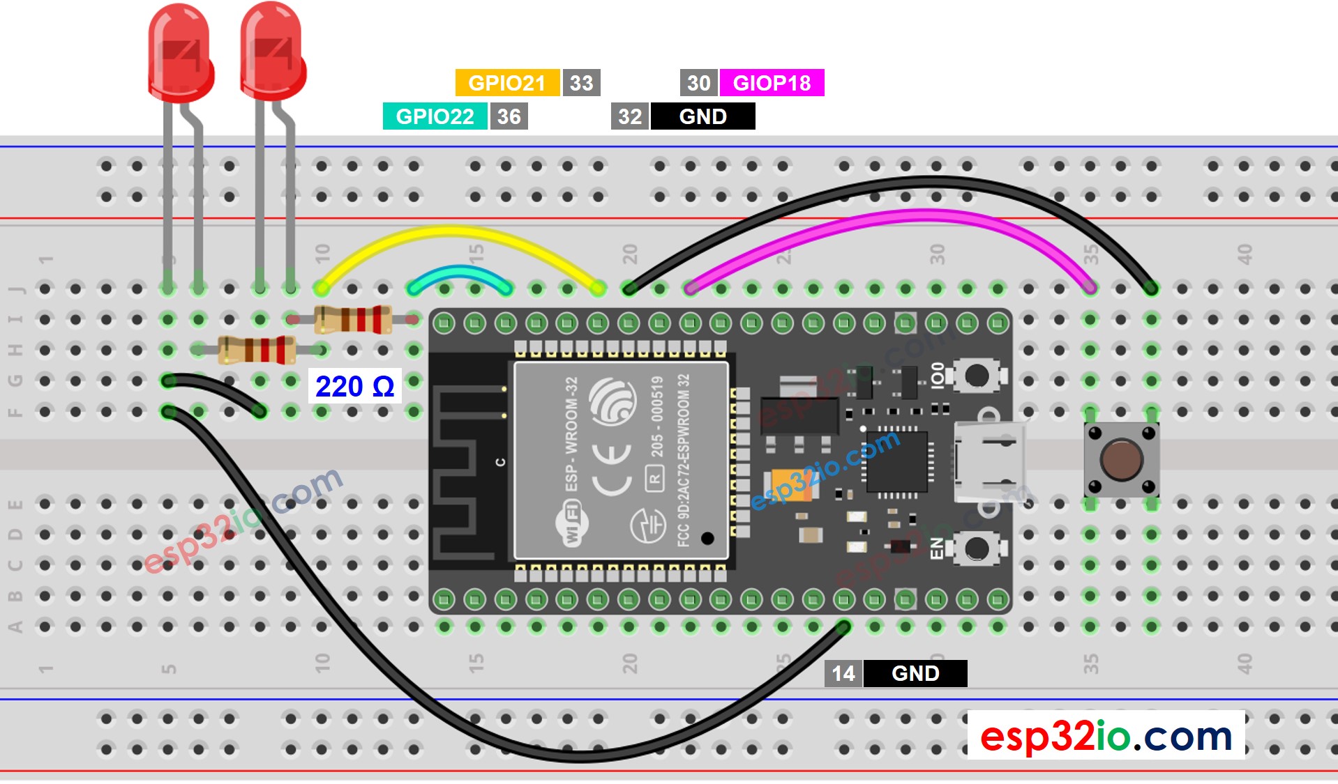
This image is created using Fritzing. Click to enlarge image
Video Tutorial
Estamos considerando crear tutoriales en video. Si considera que los tutoriales en video son importantes, suscríbase a nuestro canal de YouTube para motivarnos a crear los videos.