ESP8266 - Zumbador piezoeléctrico con potenciómetro

Este tutorial explica cómo usar el ESP8266 y un potenciómetro para controlar un zumbador piezoeléctrico. En detalle:

Acerca del zumbador piezoeléctrico y del potenciómetro

Si no está familiarizado con el diagrama de pines, el funcionamiento y la programación de zumbadores piezoeléctricos y potenciómetros, los siguientes tutoriales pueden ayudar:

Diagrama de Cableado

Diagrama de cableado del ESP8266 NodeMCU, potenciómetro y zumbador piezoeléctrico

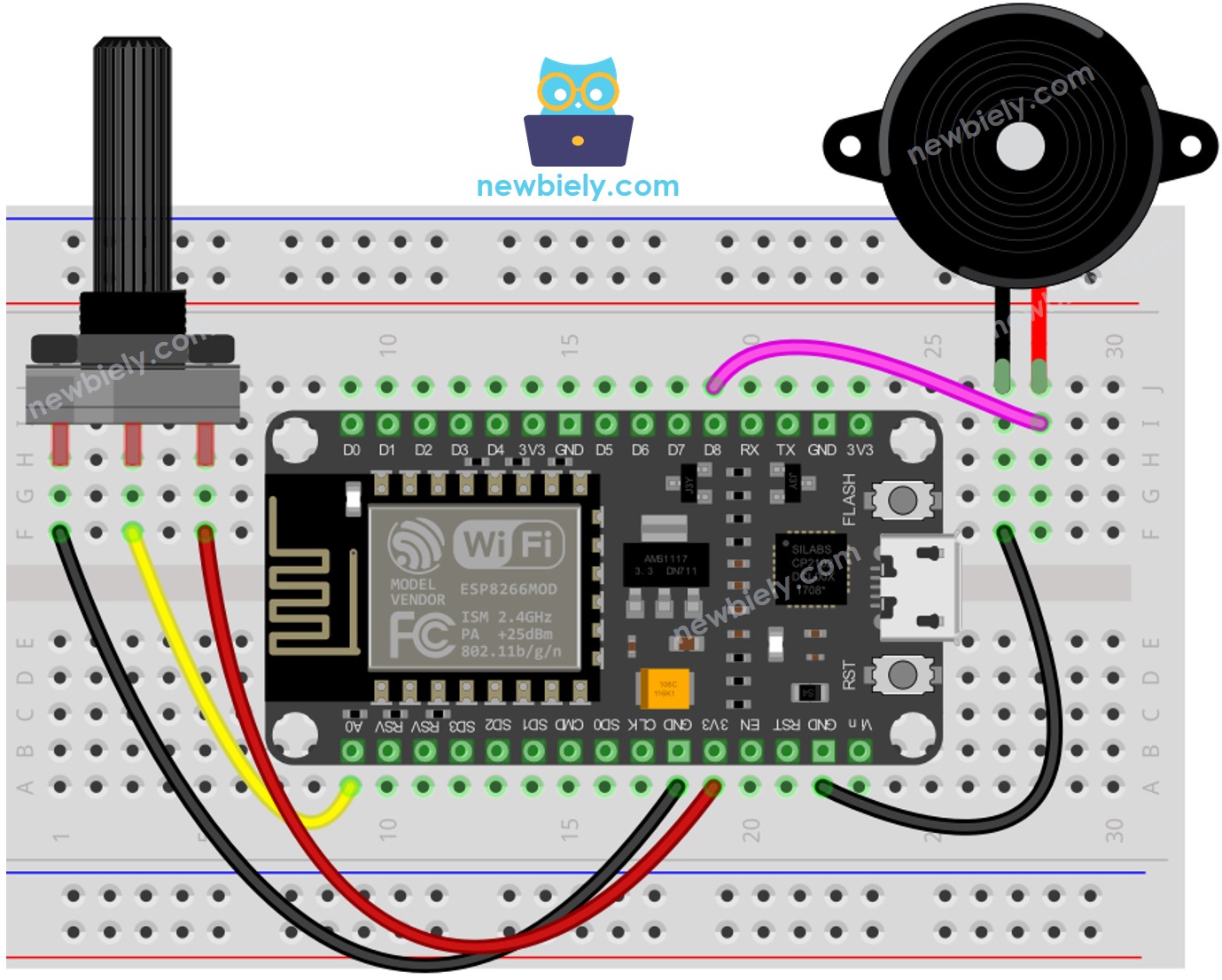
This image is created using Fritzing. Click to enlarge image

Para obtener m\u00e1s informaci\u00f3n, consulte Pines del ESP8266 y c\u00f3mo alimentar ESP8266 y otros componentes.

ESP8266 Código - Sonido Simple - Umbral Analógico

/* * Este código de ESP8266 NodeMCU fue desarrollado por es.newbiely.com * Este código de ESP8266 NodeMCU se proporciona al público sin ninguna restricción. * Para tutoriales completos y diagramas de cableado, visite: * https://es.newbiely.com/tutorials/esp8266/esp8266-potentiometer-piezo-buzzer */ #define POTENTIOMETER_PIN A0 // The ESP8266 pin connected to Potentiometer pin #define BUZZER_PIN D8 // The ESP8266 pin connected to Buzzer's pin #define ANALOG_THRESHOLD 1000 void setup() { pinMode(BUZZER_PIN, OUTPUT); // Configure the ESP8266 pin to the output mode } void loop() { int analog_value = analogRead(POTENTIOMETER_PIN); // read the input on analog pin if (analog_value > ANALOG_THRESHOLD) digitalWrite(BUZZER_PIN, HIGH); // turn on Piezo Buzzer else digitalWrite(BUZZER_PIN, LOW); // turn off Piezo Buzzer }

Pasos R\u00e1pidos

Para empezar con ESP8266 en Arduino IDE, siga estos pasos:

  • Consulta el tutorial cómo configurar el entorno para ESP8266 en Arduino IDE si es la primera vez que usas ESP8266.
  • Conecta los componentes como se muestra en el diagrama.
  • Conecta la placa ESP8266 a tu computadora usando un cable USB.
  • Abre Arduino IDE en tu computadora.
  • Elige la placa ESP8266 correcta, como (p. ej. NodeMCU 1.0 (ESP-12E Module)), y su puerto COM respectivo.
  • Conecta el ESP8266 NodeMCU a la computadora usando un cable USB.
  • Abre el Arduino IDE, elige la placa y el puerto correctos.
  • Copia el código y ábrelo en el Arduino IDE.
  • Haz clic en el botón Subir en el Arduino IDE para enviar el código al ESP8266.
  • Gira el potenciómetro.
  • Escucha el sonido que sale del zumbador piezoeléctrico.

Explicación del código

¡Echa un vistazo a la explicación línea por línea contenida en los comentarios del código fuente!

Código ESP8266 - Sonido simple - Umbral de voltaje

El valor analógico de un potenciómetro se convierte en un voltaje. A continuación, este voltaje se compara con un umbral de voltaje, lo que activará el zumbador piezoeléctrico si se excede el umbral.

/* * Este código de ESP8266 NodeMCU fue desarrollado por es.newbiely.com * Este código de ESP8266 NodeMCU se proporciona al público sin ninguna restricción. * Para tutoriales completos y diagramas de cableado, visite: * https://es.newbiely.com/tutorials/esp8266/esp8266-potentiometer-piezo-buzzer */ #define POTENTIOMETER_PIN A0 // The ESP8266 pin connected to Potentiometer pin #define BUZZER_PIN D8 // The ESP8266 pin connected to Buzzer's pin #define VOLTAGE_THRESHOLD 2.5 // Voltages void setup() { pinMode(BUZZER_PIN, OUTPUT); // Configure the ESP8266 pin to the output mode } void loop() { int analog_value = analogRead(POTENTIOMETER_PIN); // read the input on analog pin float voltage = floatMap(analog_value, 0, 1023, 0, 5); // Rescale to potentiometer's voltage if (voltage > VOLTAGE_THRESHOLD) digitalWrite(BUZZER_PIN, HIGH); // turn on Piezo Buzzer else digitalWrite(BUZZER_PIN, LOW); // turn off Piezo Buzzer } float floatMap(float x, float in_min, float in_max, float out_min, float out_max) { return (x - in_min) * (out_max - out_min) / (in_max - in_min) + out_min; }

Código ESP8266 - Melodía - Umbral de voltaje

/* * Este código de ESP8266 NodeMCU fue desarrollado por es.newbiely.com * Este código de ESP8266 NodeMCU se proporciona al público sin ninguna restricción. * Para tutoriales completos y diagramas de cableado, visite: * https://es.newbiely.com/tutorials/esp8266/esp8266-potentiometer-piezo-buzzer */ #include "pitches.h" #define POTENTIOMETER_PIN A0 // The ESP8266 pin connected to Potentiometer pin #define BUZZER_PIN D8 // The ESP8266 pin connected to Buzzer's pin #define VOLTAGE_THRESHOLD 2.5 // Voltages // notes in the melody: int melody[] = { NOTE_E5, NOTE_E5, NOTE_E5, NOTE_E5, NOTE_E5, NOTE_E5, NOTE_E5, NOTE_G5, NOTE_C5, NOTE_D5, NOTE_E5, NOTE_F5, NOTE_F5, NOTE_F5, NOTE_F5, NOTE_F5, NOTE_E5, NOTE_E5, NOTE_E5, NOTE_E5, NOTE_E5, NOTE_D5, NOTE_D5, NOTE_E5, NOTE_D5, NOTE_G5 }; // note durations: 4 = quarter note, 8 = eighth note, etc, also called tempo: int noteDurations[] = { 8, 8, 4, 8, 8, 4, 8, 8, 8, 8, 2, 8, 8, 8, 8, 8, 8, 8, 16, 16, 8, 8, 8, 8, 4, 4 }; void setup() { } void loop() { int analog_value = analogRead(POTENTIOMETER_PIN); // read the input on analog pin float voltage = floatMap(analog_value, 0, 1023, 0, 5); // Rescale to potentiometer's voltage if (voltage > VOLTAGE_THRESHOLD) playMelody(); // play a song } float floatMap(float x, float in_min, float in_max, float out_min, float out_max) { return (x - in_min) * (out_max - out_min) / (in_max - in_min) + out_min; } void playMelody() { // iterate over the notes of the melody: int size = sizeof(noteDurations) / sizeof(int); for (int thisNote = 0; thisNote < size; thisNote++) { // to calculate the note duration, take one second divided by the note type. //e.g. quarter note = 1000 / 4, eighth note = 1000/8, etc. int noteDuration = 1000 / noteDurations[thisNote]; tone(BUZZER_PIN, melody[thisNote], noteDuration); // to distinguish the notes, set a minimum time between them. // The note's duration + 30% seems to work well: int pauseBetweenNotes = noteDuration * 1.30; delay(pauseBetweenNotes); // stop the tone playing: noTone(BUZZER_PIN); } }

Pasos R\u00e1pidos

  • Conecta los componentes como se muestra en el diagrama.
  • Conecta la placa ESP8266 a tu computadora usando un cable USB.
  • Abre Arduino IDE en tu computadora.
  • Elige la placa ESP8266 correcta, como (p. ej. NodeMCU 1.0 (ESP-12E Module)), y su puerto COM respectivo.
  • Copia el código y ábrelo con Arduino IDE.
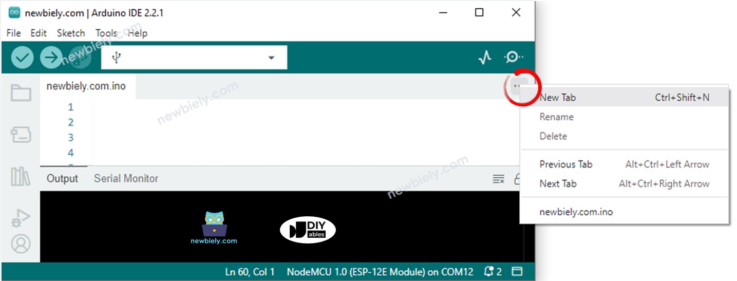
  • Crea el archivo pitches.h en Arduino IDE haciendo:
    • Haz clic en el botón justo debajo del icono del monitor serie y elige Nueva pestaña, o usa las teclas Ctrl+Shift+N.
    Arduino IDE 2 añade archivo
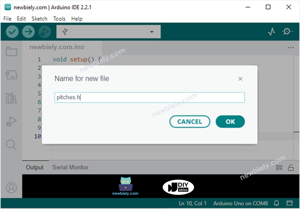
    • Escribe el nombre del archivo pitches.h y haz clic en el botón Aceptar
    Arduino IDE 2 añade el archivo pitches.h
    • Copia el código de abajo y pégalo en el archivo creado pitches.h.
    /************************************************* * Public Constants *************************************************/ #define NOTE_B0 31 #define NOTE_C1 33 #define NOTE_CS1 35 #define NOTE_D1 37 #define NOTE_DS1 39 #define NOTE_E1 41 #define NOTE_F1 44 #define NOTE_FS1 46 #define NOTE_G1 49 #define NOTE_GS1 52 #define NOTE_A1 55 #define NOTE_AS1 58 #define NOTE_B1 62 #define NOTE_C2 65 #define NOTE_CS2 69 #define NOTE_D2 73 #define NOTE_DS2 78 #define NOTE_E2 82 #define NOTE_F2 87 #define NOTE_FS2 93 #define NOTE_G2 98 #define NOTE_GS2 104 #define NOTE_A2 110 #define NOTE_AS2 117 #define NOTE_B2 123 #define NOTE_C3 131 #define NOTE_CS3 139 #define NOTE_D3 147 #define NOTE_DS3 156 #define NOTE_E3 165 #define NOTE_F3 175 #define NOTE_FS3 185 #define NOTE_G3 196 #define NOTE_GS3 208 #define NOTE_A3 220 #define NOTE_AS3 233 #define NOTE_B3 247 #define NOTE_C4 262 #define NOTE_CS4 277 #define NOTE_D4 294 #define NOTE_DS4 311 #define NOTE_E4 330 #define NOTE_F4 349 #define NOTE_FS4 370 #define NOTE_G4 392 #define NOTE_GS4 415 #define NOTE_A4 440 #define NOTE_AS4 466 #define NOTE_B4 494 #define NOTE_C5 523 #define NOTE_CS5 554 #define NOTE_D5 587 #define NOTE_DS5 622 #define NOTE_E5 659 #define NOTE_F5 698 #define NOTE_FS5 740 #define NOTE_G5 784 #define NOTE_GS5 831 #define NOTE_A5 880 #define NOTE_AS5 932 #define NOTE_B5 988 #define NOTE_C6 1047 #define NOTE_CS6 1109 #define NOTE_D6 1175 #define NOTE_DS6 1245 #define NOTE_E6 1319 #define NOTE_F6 1397 #define NOTE_FS6 1480 #define NOTE_G6 1568 #define NOTE_GS6 1661 #define NOTE_A6 1760 #define NOTE_AS6 1865 #define NOTE_B6 1976 #define NOTE_C7 2093 #define NOTE_CS7 2217 #define NOTE_D7 2349 #define NOTE_DS7 2489 #define NOTE_E7 2637 #define NOTE_F7 2794 #define NOTE_FS7 2960 #define NOTE_G7 3136 #define NOTE_GS7 3322 #define NOTE_A7 3520 #define NOTE_AS7 3729 #define NOTE_B7 3951 #define NOTE_C8 4186 #define NOTE_CS8 4435 #define NOTE_D8 4699 #define NOTE_DS8 4978
    • Haz clic en el botón Subir en el IDE de Arduino para compilar y cargar el código al ESP8266.
    • Gira el potenciómetro.
    • Escucha la melodía del zumbador piezoeléctrico.

    Explicación del código

    ¡Consulta la explicación línea por línea contenida en los comentarios del código fuente!

    ※ Nota:

    El código anterior utiliza la función delay(). Esto tiene el efecto de bloquear otro código mientras se reproduce una melodía. Para evitar esto, la biblioteca ezBuzzer puede usarse en su lugar. Esta biblioteca fue diseñada específicamente para permitir que un zumbador emita pitidos o reproduzca una melodía sin bloquear otro código.

Video Tutorial

Estamos considerando crear tutoriales en video. Si considera que los tutoriales en video son importantes, suscríbase a nuestro canal de YouTube para motivarnos a crear los videos.

※ NUESTROS MENSAJES

  • No dude en compartir el enlace de este tutorial. Sin embargo, por favor no use nuestro contenido en otros sitios web. Hemos invertido mucho esfuerzo y tiempo en crear el contenido, ¡por favor respete nuestro trabajo!