ESP8266 - reloj OLED
Este tutorial te enseña cómo crear un reloj OLED usando ESP8266, un módulo RTC y una pantalla OLED. El tutorial proporciona instrucciones para los módulos RTC DS3231 y DS1307. En detalle:
- ESP8266 obtiene la hora, los minutos y los segundos de un módulo RTC DS3231 y las muestra en un OLED
- ESP8266 obtiene la hora, los minutos y los segundos de un módulo RTC DS1307 y las muestra en un OLED
Puede elegir uno de dos módulos RTC: DS3231 y DS1307. Para obtener más información, consulte DS3231 vs DS1307.
Hardware Requerido
Or you can buy the following kits:
| 1 | × | DIYables Sensor Kit (30 sensors/displays) | |
| 1 | × | DIYables Sensor Kit (18 sensors/displays) |
Acerca del módulo RTC OLED, DS3231 y DS1307
Si no estás familiarizado con OLED, DS3231 y DS1307 (diagrama de pines, funcionamiento, programación...), los siguientes tutoriales pueden ayudarte:
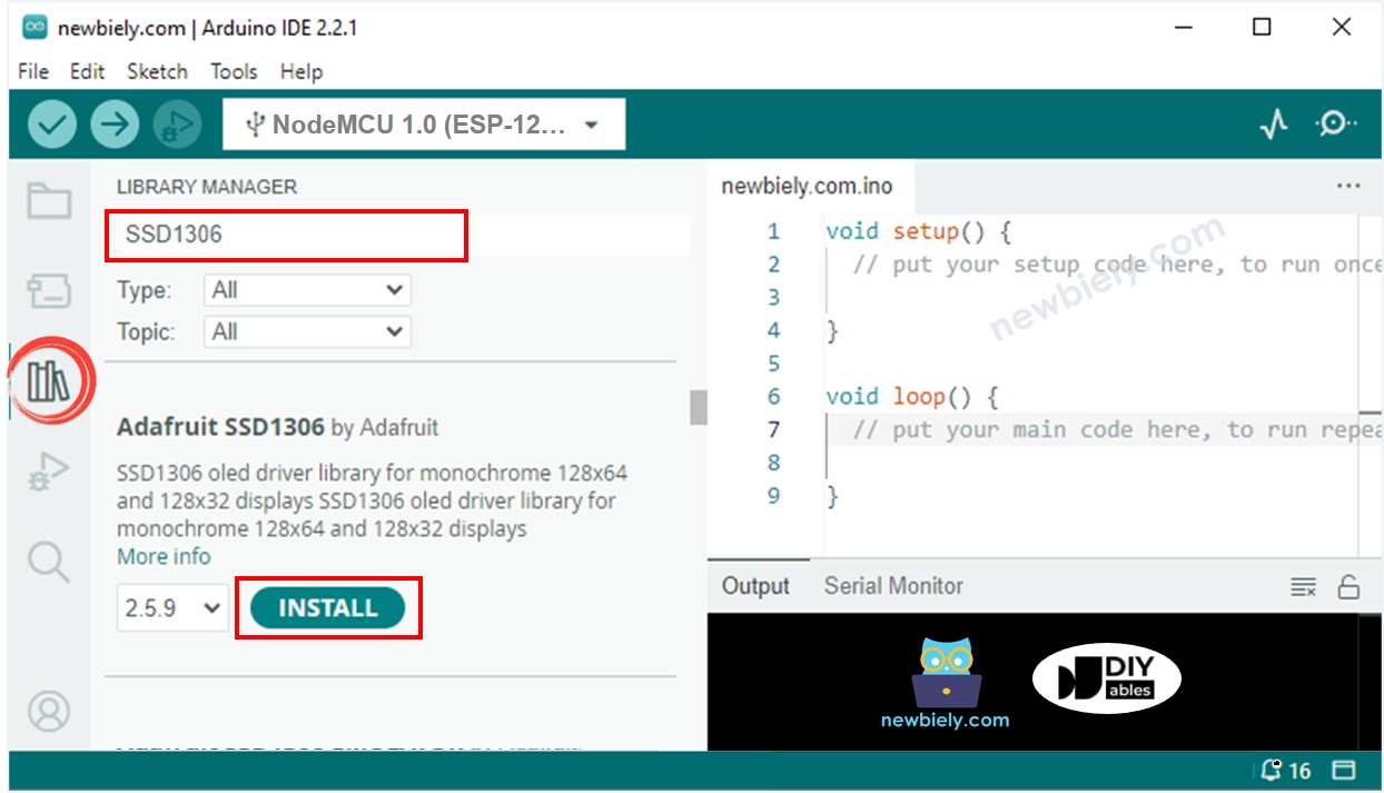
Instalar bibliotecas OLED y RTC
- Haz clic en el icono de Bibliotecas en la barra izquierda del IDE de Arduino.
- Busca “SSD1306” y localiza la biblioteca SSD1306 de Adafruit.
- Luego, pulsa el botón Instalar para completar la instalación.
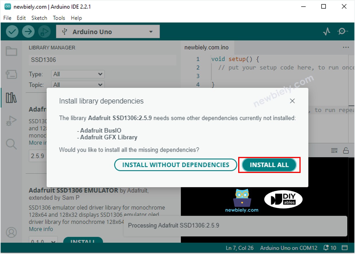
- Se le pedirá que instale dependencias de bibliotecas adicionales.
- Para instalarlas todas de una vez, haga clic en el botón Instalar todo.
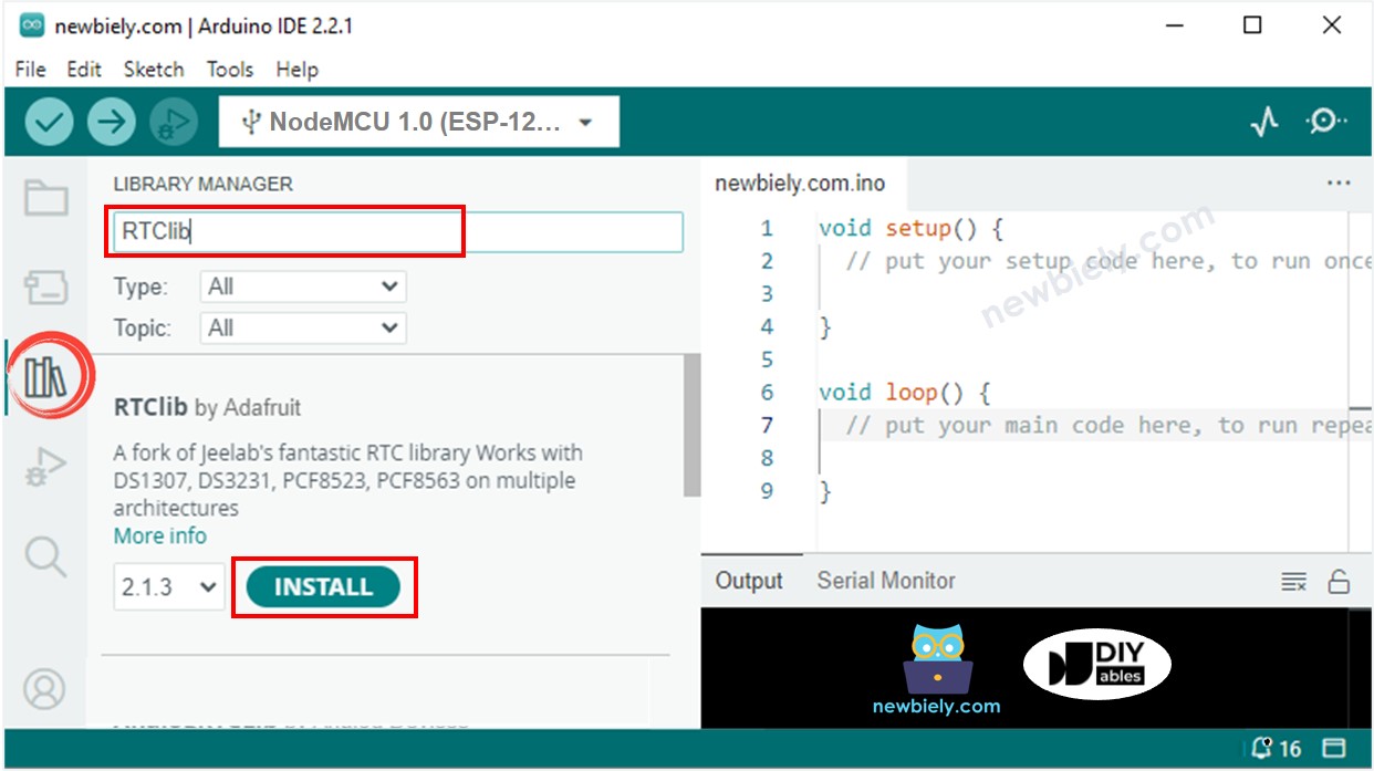
- Busca “RTClib” y localiza la biblioteca RTC de Adafruit. Esta biblioteca es compatible con ambos DS3231 y DS1307.
- Presiona el botón Instalar para instalar la biblioteca RTC.
Lectura de la hora desde el módulo RTC DS3231 y mostrarla en la pantalla OLED
Diagrama de cableado
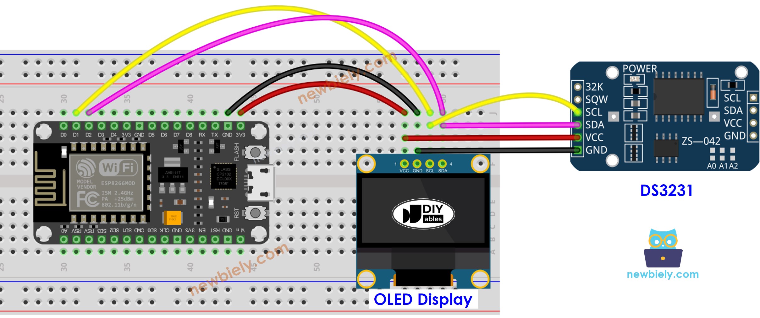
This image is created using Fritzing. Click to enlarge image
Para obtener m\u00e1s informaci\u00f3n, consulte Pines del ESP8266 y c\u00f3mo alimentar ESP8266 y otros componentes.
Código ESP8266 - DS3231 y OLED
Pasos R\u00e1pidos
Para empezar con ESP8266 en Arduino IDE, sigue estos pasos:
- Consulta el tutorial cómo configurar el entorno para ESP8266 en Arduino IDE si es tu primera vez usando ESP8266.
- Conecta los componentes tal como se muestran en el diagrama.
- Conecta la placa ESP8266 a tu ordenador utilizando un cable USB.
- Abre Arduino IDE en tu ordenador.
- Elige la placa ESP8266 correcta, como (p. ej. NodeMCU 1.0 (ESP-12E Module)), y su puerto COM correspondiente.
- Copia el código y ábrelo con el Arduino IDE.
- Haz clic en el botón Subir en el Arduino IDE para enviar el código al ESP8266.
- Coloca el sensor en agua caliente y fría, o sostenlo en tu mano.
- Consulta el resultado en la pantalla OLED.
Lectura de la hora desde el módulo RTC DS1307 y mostrarla en OLED
Diagrama de cableado
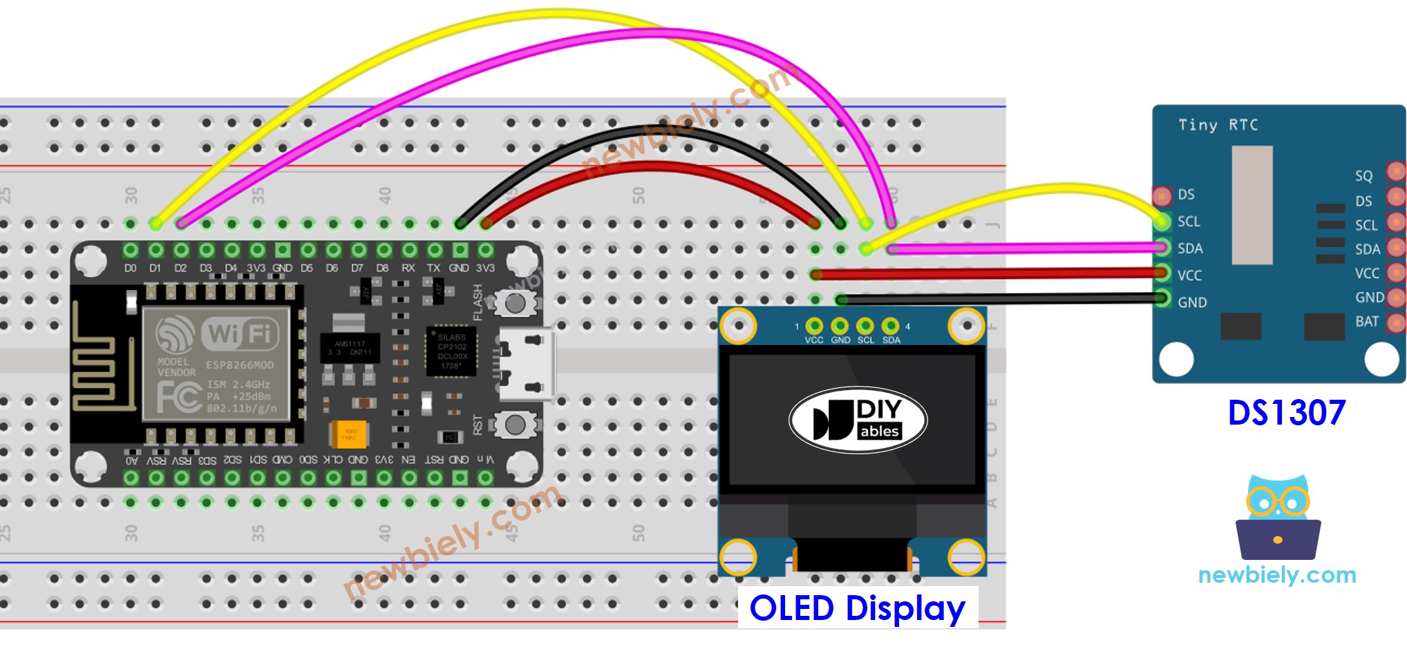
This image is created using Fritzing. Click to enlarge image
Código ESP8266 - DS1307 y OLED
Pasos R\u00e1pidos
- Conecta los componentes como se muestra en el diagrama.
- Conecta la placa ESP8266 a tu computadora usando un cable USB.
- Abre el IDE de Arduino en tu computadora.
- Elige la placa ESP8266 correcta, como (p. ej. NodeMCU 1.0 (Módulo ESP-12E)), y su puerto COM respectivo.
- Copia el código y ábrelo en el IDE de Arduino.
- Haz clic en el botón Subir para transferir el código al ESP8266.
- Coloca el sensor en agua caliente y en agua fría, o sostenlo en tu mano.
- Verifica el resultado en el OLED.
Video Tutorial
Estamos considerando crear tutoriales en video. Si considera que los tutoriales en video son importantes, suscríbase a nuestro canal de YouTube para motivarnos a crear los videos.